
The best way to understand Internet Protocol version 4 (IPv4) is to know the IPv4 header and all its fields. Segments from Transmission Control Protocol (TCP) or User Datagram Protocol (UDP) are passed on to IP for processing. The IP header is appended to the TCP or UDP segment. The TCP or UDP segment then becomes the IP data. The IPv4 header is 20 bytes in length when it uses no optional fields. The IP header includes the addresses of the sending host and the destination host. It also includes the upper-layer protocol, a field for prioritization, and a field for fragmentation. Figure 1-1 shows the IP header format.
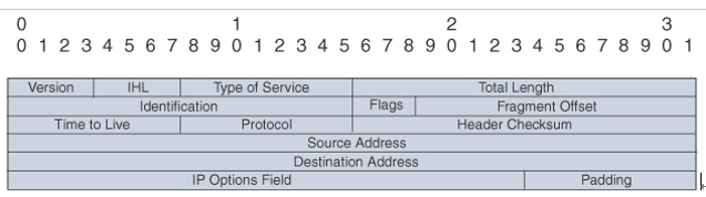
Figure 1-1 IP Header
The following is a description of each field in the IP header:
- Version: This field is 4 bits in length. It indicates the IP header’s format, based on the version number. Version 4 is the current version, and this field is set to 0100 (4 in binary) for IPv4 packets. The Version field is set to 0110 (6 in binary) in IPv6 networks.
- IHL (Internet Header Length): This field is 4 bits in length. It indicates the length of the header in 32-bit words (4 bytes) so that the beginning of the data can be found in the IP header. The minimum value for a valid header is 5 (0101) for five 32-bit words.
- ToS (Type of Service): This field is 8 bits in length. Quality-of-service (QoS) parameters such as IP precedence and DSCP are found in this field. (These concepts are explained later in this chapter.)
- Total Length: This field is 16 bits in length. It represents the length of the datagram, or packet, in bytes, including the header and data. The maximum length of an IP packet can be 216 − 1 = 65,535 bytes. Routers use this field to determine whether fragmentation is necessary by comparing the total length with the outgoing MTU.
- Identification: This field is 16 bits in length. It is a unique identifier that denotes fragments for reassembly into an original IP packet.
- Flags: This field is 3 bits in length. It indicates whether the packet can be fragmented and whether more fragments follow. Bit 0 is reserved and set to 0. Bit 1 indicates May Fragment (0) or Do Not Fragment (1). Bit 2 indicates Last Fragment (0) or More Fragments to Follow (1).
- Fragment Offset: This field is 13 bits in length. It indicates (in bytes) where in the packet this fragment belongs. The first fragment has an offset of 0.
- Time to Live: This field is 8 bits in length. It indicates the maximum time the packet is to remain on the network. Each router decrements this field by 1 for loop avoidance. If this field is 0, the packet must be discarded. This scheme permits routers to discard undeliverable packets.
- Protocol: This field is 8 bits in length. It indicates the upper-layer protocol. The Internet Assigned Numbers Authority (IANA) is responsible for assigning IP protocol values. Table 1-2 shows some key protocol numbers. You can find a full list at www.iana.org/assignments/protocol-numbers.
Table 1-2 IP Protocol Numbers
| Protocol Number | IP Protocol |
| 1 | Internet Control Message Protocol (ICMP) |
| 2 | Internet Group Management Protocol (IGMP) |
| 6 | Transmission Control Protocol (TCP) |
| 17 | User Datagram Protocol (UDP) |
| 41 | IPv6 encapsulation |
| 50 | Encapsulating Security Payload (ESP) |
| 51 | Authentication Header (AH) |
| 58 | ICMPv6 |
| 88 | Enhanced Interior Gateway Routing Protocol (EIGRP) |
| 89 | Open Shortest Path First (OSPF) |
| 103 | Protocol Independent Multicast (PIM) |
| 112 | Virtual Router Redundancy Protocol (VRRP) |